Product Category
Solar Energy
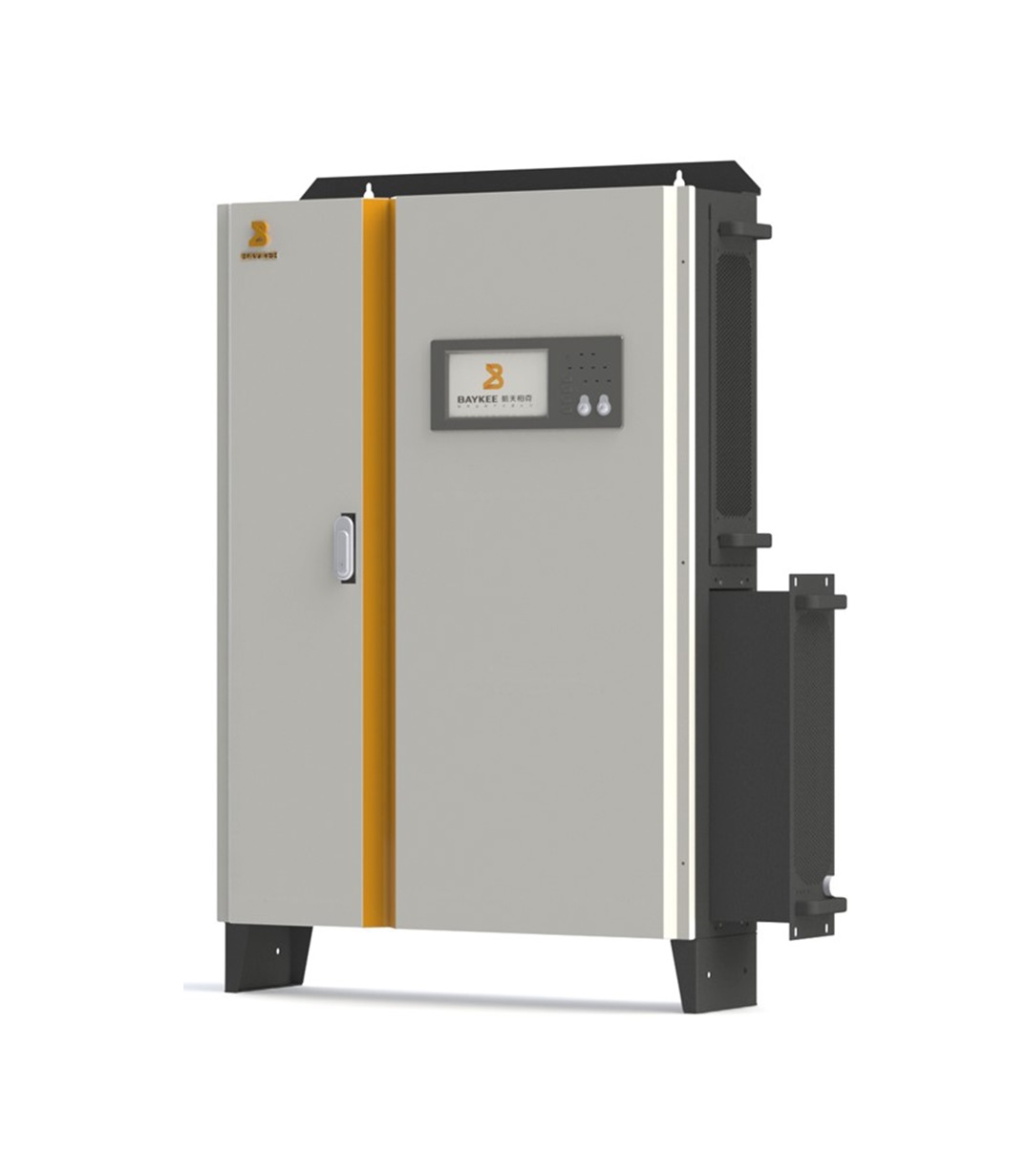


BK TYN-M MULTIMODE MODULAR HYBRID SOLAR INVERTER (10/20-800KW)
Category: Solar Energy
TYN-M Series Modular Multi-System Hybrid Solar Inverter is an Intelligent Multi-function Power Supply designed by Aerospace Baykee for New Energy needs. It is internally powered by:
• Solar MPPT Controller
• Charger
• Rectifier
• Inverter
• Static Switch
• Main Control Circuit
• Display Alarm Circuit
Applications:
• Grid-tie System
• Off-Grid System
• Hybrid System
• On-Grid Hybrid System
• Off-Grid Hybrid System
Salient Features:
- Multimode-Standard Design
- Modular Technology: For easy Expansion and Redundancy
- Hot Swappable: Reduce On-Site Repair and Maintenance time
- High-Speed Static Switching
- Bus MPPT Control Technology
- Reverse Feeding Management
- Intelligent Input Source Management
- Large Touch Screen Display
- User-Friendly Configuration: Parallel Operation up to 800 KW
- Current Limiting Soft-Start Circuit: to reduce the Inrush Current
- Intelligent Digital Control Technology: High-Speed DSP Microcontroller
- Sixth Generation High-Speed Low-Loss IGBT
- Intelligent Fault Detection Function and Communication
- Superior Load Characteristics: 0 to 100% load transition without switching to bypass
- High-Performance Dynamic Regulation: reduce output voltage distortion
- Optional Battery Inspection Module
Basic System Topology:
The hybrid solar inverter power system consists of solar energy (including photovoltaic modules, solar installation bracket, PV combiner box, etc.), mains power, multi-mode modular inverter (including MPPT controller, inverter, static bypass), battery pack, and battery management system, and input, output distribution, etc. This inverter can power all kinds of appliances in-home or office environments, including motor-type appliances. The input sources can be Grid, Genset, or Solar. For backup, Lithium-Ion Battery Bank is used with Battery Management System (BMS). Cloud Monitoring enables users to remotely monitor the system. The following illustration shows the basic system topology for the TYN-M inverter.

The Working Principle:
Basic Circuit Diagram of BK TYN-M Inverter shows the path followed by energy to flow in different working modes of the system.

| PARAMETER | BK-TYN-M-10K | BK-TYN-M-20K | BK-TYN-M-60K | BK-TYN-M-100K | BK-TYN-M-200K |
|---|---|---|---|---|---|
| Rated Output Power | 10KW | 20KW | 60KW | 100KW | 200KW |
| Operating Mode | Solar Energy, AC Hybrid Energy STorage Inverter Power Supply | ||||
| Working Order | Solar Energy——Grid——Battery | ||||
| Technology | High Frequency | ||||
| Isolation Transformer | Optional | ||||
| Power Module Model | TYNM-20K-PM | ||||
| Configurable number of Power Modules | 1 Set | 1~3 Set | 1~5 Set | 1~10 Set | |
| SOLAR ENERGY | |||||
| Maximum Input Power | 5KW×2 | 10KW×2 | 10KW×6 | 10KW×10 | 10KW×20 |
| Rated Operating Voltage | 500V | ||||
| Maximum Input Voltage | 800V | ||||
| MPPT Range | 400~800V | ||||
| Maximum Input Current | 20A×2 | ||||
| Number of Input Channels | 2 Channels | 6 Channels | 10 Channels | 20 Channels | |
| MAINS(CONVERTER) | |||||
| Rated Operating Voltage | L-L:380/400/415 Vac,L-N:220/230/240 Vac 3Phase 4Wire(or single phase 2 wire) + PE | ||||
| Rated Operating Frequency | 50/60Hz | ||||
| Input Voltage Range | ±25%,-40%(Half Load) | ||||
| Input Frequency Range | ±10% | ||||
| Input Power Factor | ≥0.95(20~50% Load)≥0.99(100% Load) | ||||
| Total Harmonics Distortion (THD)(2~39 times) | ≤3%(100% Load) | ||||
| Maximum Input Power | 15KW | 30KW | 90KW | 150KW | 300KW |
| Maximum Output Power | 10KW | 20KW | 60KW | 100KW | 200KW |
| Maximum Input Current | 22.5A | 45A | 135A | 225A | 450A |
| Grid Current DC Component | ≤0.5% Rated DC Current | ||||
| Isolation Protection Time | 2s | ||||
| Generator Mode | Yes | ||||
| OUTPUT(INVERTER) | |||||
| Rated Operating Voltage | L-L:380/400/415 Vac,L-N:220/230/240 Vac 3Phase 4Wire(or single phase 2 wire) + PE | ||||
| Rated Operating Frequency | 50/60Hz±0.5Hz | ||||
| Output Regulation Accuracy | ≤±1% | ||||
| Frequency Tracking Rate | 0.2Hz/s~2Hz/s | ||||
| Waveform Distortion | Sine Wave, Distortion:≤3%(Linear Load)≤5%(Non Linear Load) | ||||
| Output DC Component | ≤1% | ||||
| Three Phase Voltage Phase Deviation | 2º | ||||
| Dynamic Transient Characteristics | Inverter output dynamic transient range is less than ±10%,Transient recovery time <20mS | ||||
| Crest Factor | 3:1 | ||||
| Overload Capability | 1 minute delay for 125% overloading, Immediate Protection at150% Overloading | ||||
| Working Standard | Three In Three Out, Three In Single Out, Single In Single Out, Single In Three Out (Optional) | ||||
| Operation Mode | ON-Grid/OFF Grid/Hybrid Mode | ||||
| Parallel No Load Circulation | ≤5% | ||||
| Parallel Current Imbalance | ≤5% | ||||
| Self-Aging Function | 25%,50%,75%,100%(Four Set Optional) | ||||
| BATTERY | |||||
| Rated Voltage | 240V (192V~288V Adjustable) | ||||
| Maximum Current | 60A | 120A | 360A | 600A | 1200A |
| Battery Type | Lead Acid Battery, Lithium Battery (Or similar one) | ||||
| Battery Capacity | Configurable | ||||
| Charging Mode | Temperature-compensated constant current, Constant pressure (three-stage @ lead-acid battery) | ||||
| Floating Charge | 2.25V±1% /cell(@25℃, Lead-acid batteries) | ||||
| Average Charging Voltage | 2.34V±1% /cell(@25℃, Lead-acid batteries) | ||||
| Temperature Compensation | -3mV/℃/cell(@Lead-acid batteries) | ||||
| Maximum Charging Power | ≤50%(Adjustable),Scalable external isolation charger | ||||
| SYSTEM PARAMETERS | |||||
| Switching Time | 0ms | ||||
| Inverter Efficiency | ≥95% | ||||
| Protection | Reverse battery protection, PV reverse connection protection, output short circuit, overload, over and under voltage, phase sequence, over temperature, fan failure, etc. | ||||
| Heat Dissipation Method | Temperature-controlled air cooling | ||||
| Protection Level | IP20 | ||||
| Operating Environment | Temperature -20~50℃ | ||||
| Relative Humidity | 30%~95%(No condensation) | ||||
| Operational Height (Max.) | <1000 m(1% decrease in power per 100 meters, Maximum Height 4000 m) | ||||
| Isolation Transformer | Optional | ||||
| Installation Method | Based on customer’s requirements and the project site condition | ||||
| Dimension W*D*H (mm) | 800*200*1100 | 600*800* 1200 | 600*800* 1800 | 600*800* 2200 | |